|
Vertical Electrical Survey Introduction Resistivity investigation methods utilizes the fact that different earth materials display a characteristic resistance to the flow of an electrical current. As such, the resistivity method is well suited to determine: the locations and attitudes of geologic faults; the locations and attitudes of geologic contacts; layering and discontinuities; the location and seepage around dams, the electrical resistivity's of soils and rocks; and depth to the top of the phreatic surface. Although terrain conductivity methods are generally faster and therefore more economical for areal mapping, resistivity methods have greater accuracy especially for depth determinations and inversion layer modeling. |
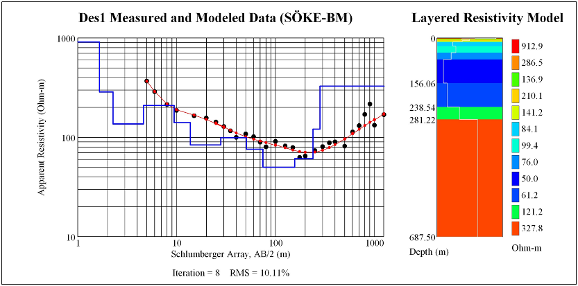
MethodologyThe typical methodology in conducting a resistivity investigation begins by some pre-modeling to determine the type of array to be selected and electrode spacing. There are two basic types of resistivity investigations profiling and depth investigations, the former will be used to detect lateral changes and the latter to investigates layering. Profiling results will be displayed as profiles which preserve the features of the original data and depth soundings will be computer modeled. |
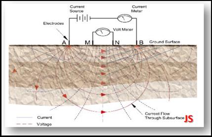

Types of ArraysChoosing the type of array in DC investigations is not only an important factor to ensure success, it also determines the efficiency of the investigation. In resistivity profiling investigations cables and electrodes are moved long distances and therefore the arrays chosen will be those which make 'moves' as simple and rapid as possible. Wenner Array Wenner array will be used for both resistivity profiling and depth sounding. It has the advantage that it is very widely used and therefore has a vast amount of interpretational material. However, in this array all four electrodes are moved making it less time efficient for profiling, but since the distances between the electrodes are small. mistakes are less likely. In the Wenner array near-surface conditions differ at all four electrodes for each reading, giving a rather high noise level. A very much smoother curve can be produced using offsetting techniques. Offsetting is achieved by setting out five equi-spaced electrodes, two readings are then taken at each expansion and averaging of the two produces a curve in which local effects are suppressed, while differencing provides estimates of the significance of those effects. Because the signal-contribution contours for the Wenner array at depth are slightly flatter than those of the Schlumberger array we will often use Wenner array for locating flat laying interfaces. Schlumberger Array Even though portability is less important in resistivity depth sounding than in profiling the Schlumberger array (where only two electrodes moved) will be used were appropriate because of speed and convenience. The plethora of interpretation material for the Schlumberger array also makes it attractive for depth sounding. Site selection is extremely important with the Schlumberger array because it is sensitive to conditions around the closely-spaced inner electrodes. Therefore, locations where the upper layer is very inhomogeneous may not be suitable for the Schlumberger array and the offset Wenner array will be used. Dipole-dipole Array This array is mainly used in IP work where induction effects must be avoided at all costs, however it is also effective in resistivity profiling. It uses four moving electrodes and is therefore less desirable also the observed voltages tend to be rather small. Although theoretically possible the dipole-dipole array will not be used for resistivity depth sounding. Polar-dipole Array The asymmetrical anomalies produced by this array are more difficult to interpret than those produced by symmetrical arrays A major problem with this array is that peaks are displaced from the centers of conductive bodies and there is no real agreement as to where the results should be plotted. Equatorial-dipole Array (Azimuthally Resistivity) The equatorial-dipole array is well suited to joint and fracture trend investigations and can be used for detailed groundwater flow modeling. The equatorial-dipole array can only be used at sites where there are large circular open spaces free of interfering conductors. Azimuthally resistivity can be very time and cumbersome when moving the array. The most efficient and accurate method of setting up the array every 10 degrees is to stake the fixed end point of the array and then using a 9.5-foot long chain and roll tape rotate about the pivot point and stake every five feet. The procedure is then repeated using a 19 foot chain and stacking every 10 feet , the end result is three stakes on which to align the array at every 10 degrees. Mise-a-la-masse Array This three point electrode system is appropriate where some part of the conductive zone is already exposed, either as an outcrop or in a drill hole. The advantage of this technique is that the extent, dip, strike and continuity of the zone will be better indicated than by conventional techniques. |
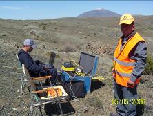
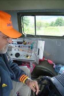


|
Home |

|
About Us |

|
Contact Us |

|
Project |

|
Referances |

|
Certificate |
|
Back Survey |

|
Equipments |

